Performance
PCM capacitor performances are well known and predictable thanks to analytical modelling, thermal tests and correlation of mathematical thermal models. Several examples are illustrated below, showing the good adequacy between test results and correlated thermal models.
Large PCM Capacitors
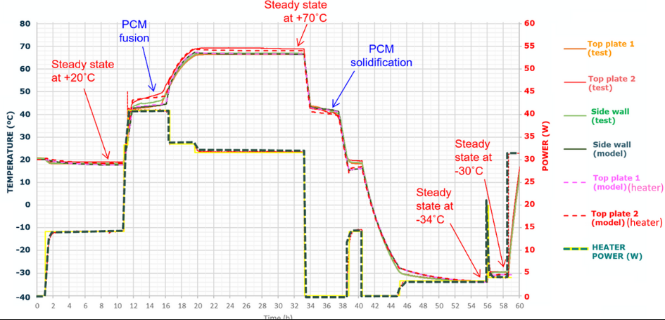
Temperature, power and heater use for the Large PCM breadboard thermal balance test
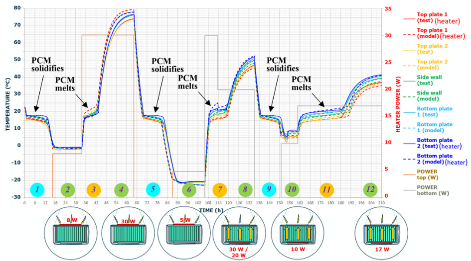
Figure above shows the overall result of the thermal balance test conducted on the large PCM capacitor breadboard. The graph depicts both the measured temperatures (solid lines) and the predicted temperatures for corresponding nodes (dotted lines), alongside the power of either the bottom side (index 2 is on the heater) or the top side (index 1 is on the heater). Additionally, the graph includes schematics illustrating the various heater configurations utilized. As illustrated in Figure below, the top heaters were positioned directly on the radiative surface of the breadboard, while the bottom heaters, located opposite the radiative side, generate heat flux that traverses the entire thickness of the breadboard. Throughout the whole test, the chamber shrouds were cooled and maintained at -75ºC. A total of 12 phases were performed (the phase numbers is indicated at the bottom of the graph). Among these phases, six (highlighted in green) were steady state, with different heaters activated at varying power levels. These phases were mainly used to adjust and correlate the model in steady state conditions, particularly regarding the couplings with the environment and internal conductances, through metallic filler and the structure. Three phases (indicated by blue numbers) involved cooling down, during which the PCM solidified. Additionally, three phases comprised transient warming up phases, involving PCM fusion, each carried out with different heaters (bottom or top plate) and power levels. Phase 7 even entailed a change in power during the PCM melting process. These transient phases were crucial for correlating latent heat, heat capacitance, and adjusting internal couplings as necessary.
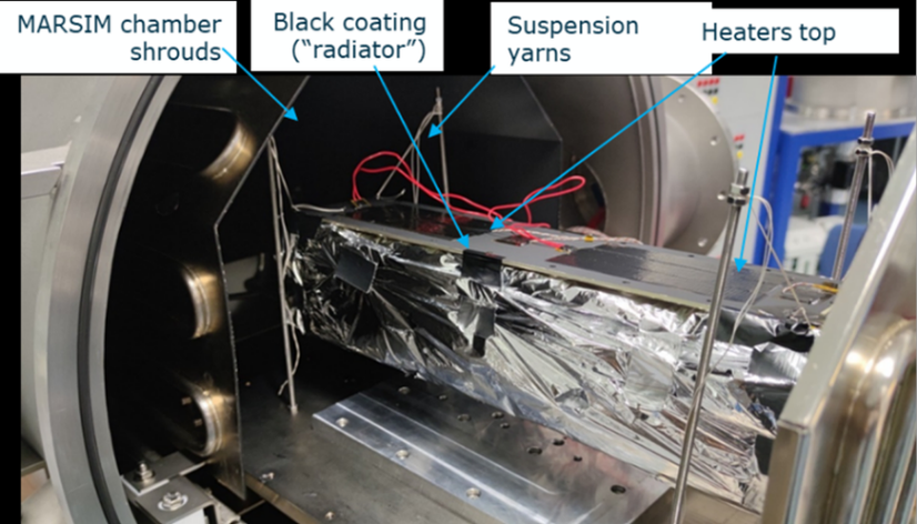
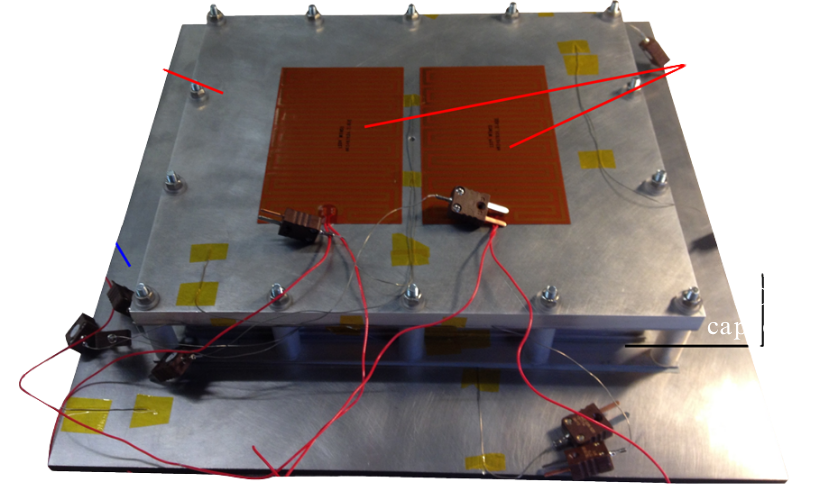
Large PCMC breadboard inside the vacuum chamber with MLI insulation and black coated top plate
Medium and Small PCM Capacitors
Temperature, power and heater use for the Medium PCM breadboard thermal balance test
PCM capacitor performances are well known and predictable thanks to analytical modelling, thermal tests and correlation of mathematical thermal model. Several examples are illustrated below, showing the good adequacy between test results and correlated thermal models.
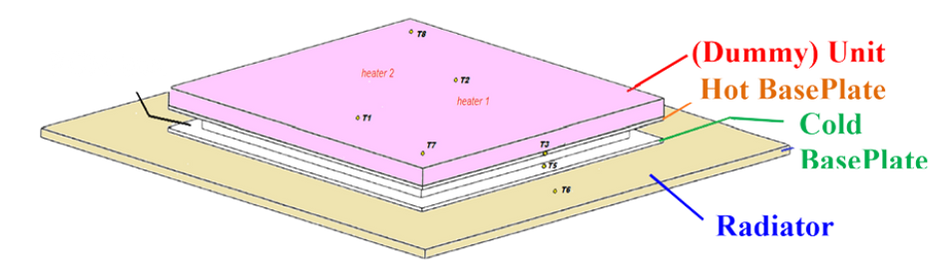
PCM capacitor with radiator and dummy unit (including heaters)
PCM Set Up for the Thermal Test
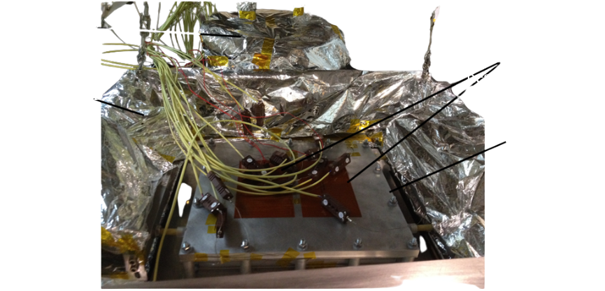
PCMC test assembly with the MLI inside the vacuum chamber
The figure below presents 2 cycles with a different heat load each superposed on a same graph to better compare the thermal performance of the PCM capacitor
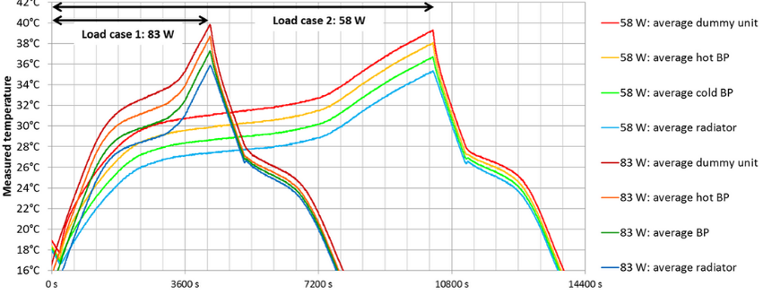
Test results: Measured temperature for 2 cycles with different a heat load each